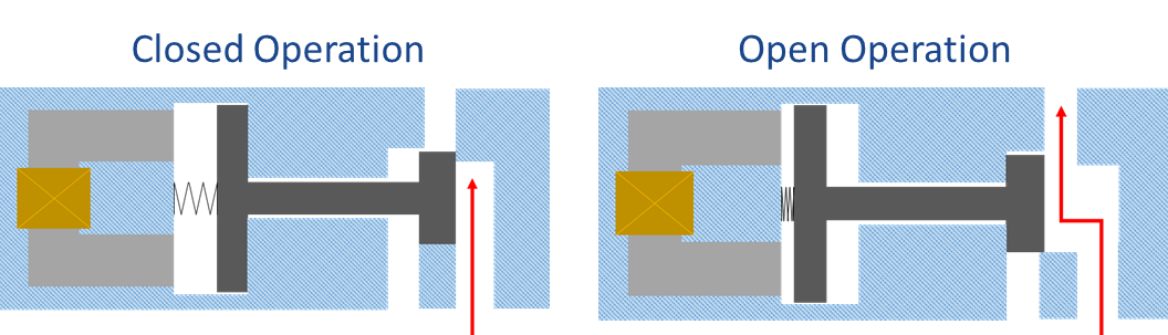
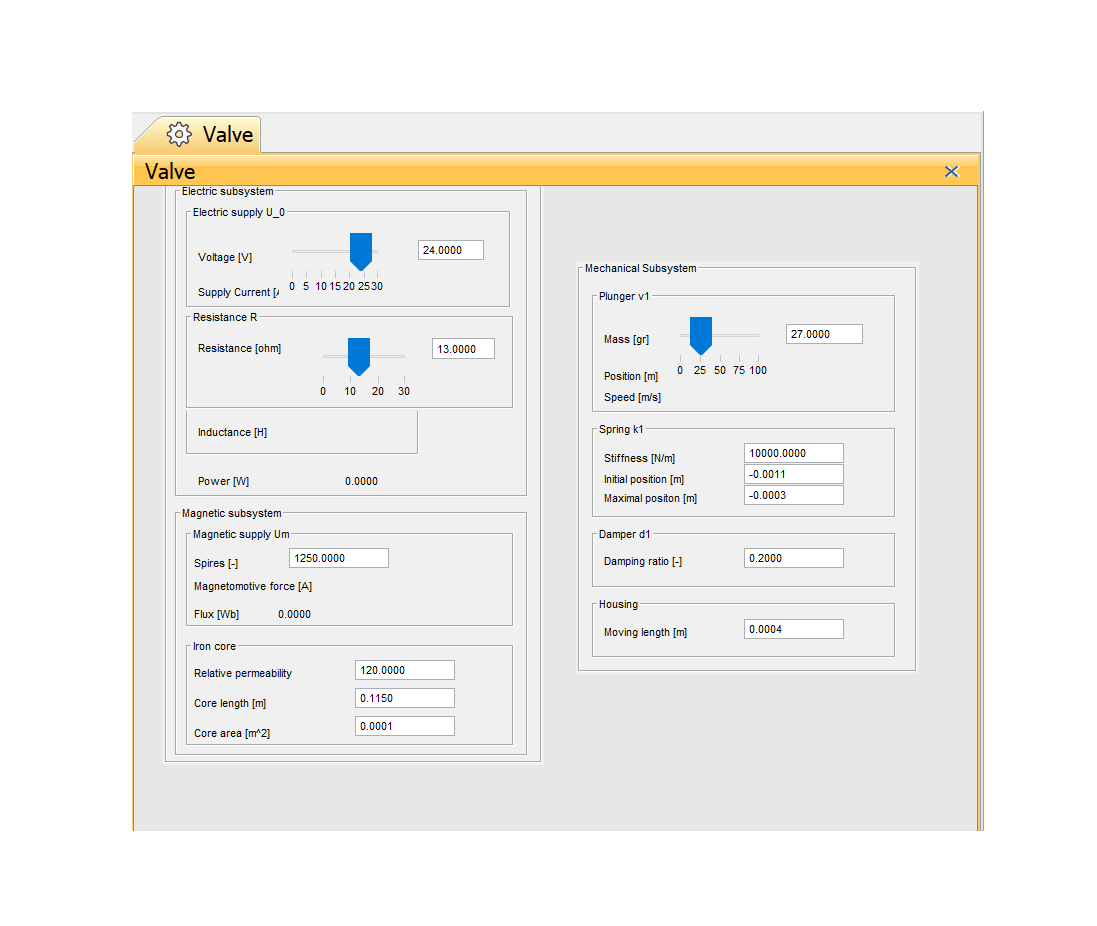
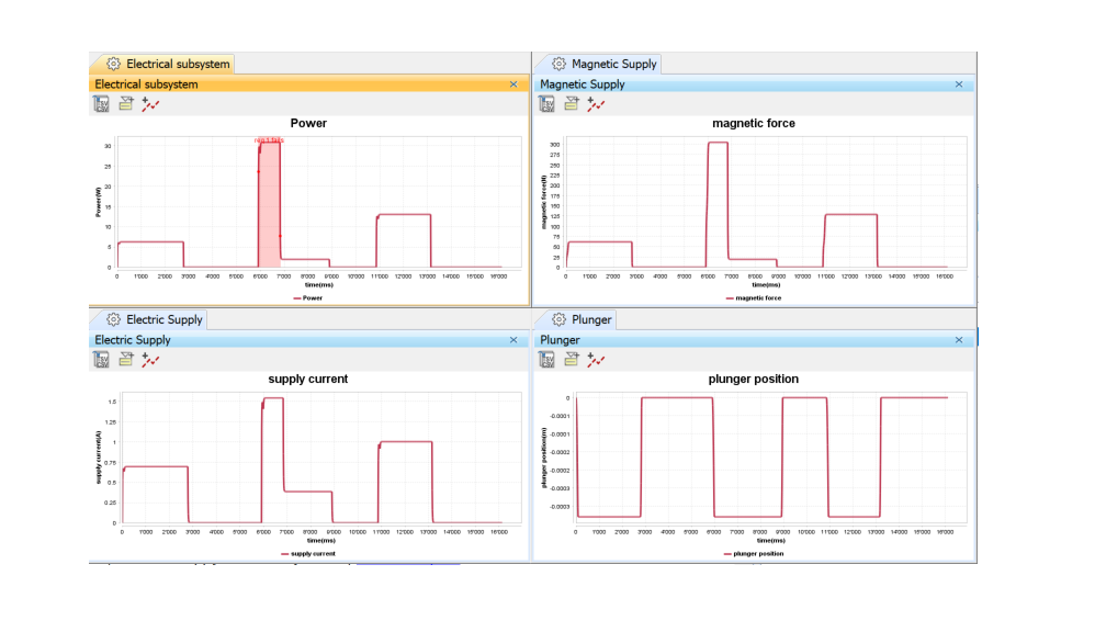
Electromechanical Valve Physical Model

This article presents an example of a valve model built by ROSAS' Model-Based Engineering department.

Expertise

Model Based Engineering, Safety & Reliability

Electromechanical valve model

The ROSAS' Model-Based Engineering (MBE) department has developed an electromechanical valve model. The model is a structured representation that focuses on the requirements, behavior, structure, properties and interconnections of a system. This model can then be simulated to extract information. In this case we were interested in the physical behavior, i.e. the various forces that come into play during the operation of this valve. It is therefore possible to design various system variants and to observe and verify their constraints such as 

  • Power (voltage and/or current limitation)
  • Dimensioning
  • Spring parameters
  • Opening/closing speeds

Objectives of the project

  • To build a physical model of valves 
  • To simulate its mechanical, fluid dynamic, electrical and magneticbehaviour in function of its operating conditions 
  • To demonstrate the concept of co-engineering between the engineeringteams around one single model  

Benefits

  • No prototype required for the co-engineering activities, all engineering tasks digitalyperformed around one single source of truth 
  • Best development quality by testing largenumbers of configuration  
  • Best product quality by testing normal and out of bounds scenarios
  • Shorter time-to-market and lower development costs

Co-simulation of two models

Two models were produced:

  • The first one, with the SysML language that we used in the Cameo System Modeler software. This model makes it possible to specify the requirements (e.g. the power shall not exceed 20W) and contains all the parameters of the valve.
  • The second model, made with the Simulink tool, is the analytical models representing the physical behavior of the valve. In order to make them communicate, a Functional Mock-up Interface (FMI) has been set up.

The execution of this solution therefore consists of a co-simulation of the two models, the SysML model injecting the input parameters via FMI into the MATLAB model and continuously testing the different requirements, and the MATLAB model solving the equations and transmitting the results to the SysML model via FMI.

Finally, we are able to predict the physical behaviour of the valve and the physical forces it must withstand. This makes it much easier for a manufacturer to test variants of their product without the need to create real prototypes. 

By continuing to browse this site, you agree to the use of cookies to improve your user experience and to provide website statistics.